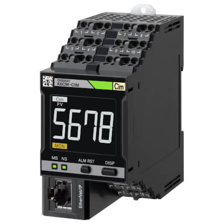
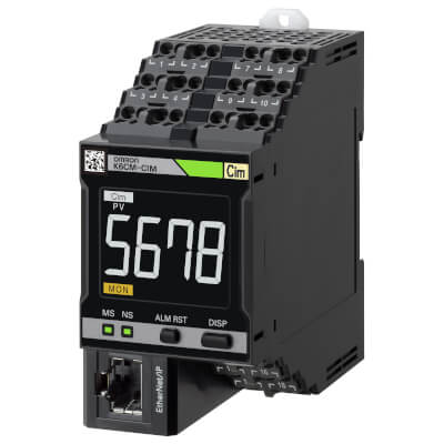
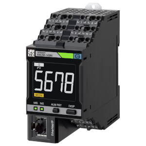
K6CM-CI2M
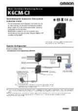
Zařízení pro monitorování stavu motoru – monitorování proudu
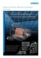
Model K6CM-CI2M je spolehlivý partner, který vám umožní předem naplánovat zásahy do údržby třífázových motorů, takže se vyhnete nákladným prostojům a zastavení výroby.
Řídicí jednotka K6CM-CI2M monitoruje křivku a spektrum proudu, což jsou velmi účinné ukazatele stavu hnací soustavy celého motoru, a navrhuje údržbu vždy, když je zjištěna jakákoli odchylka od normálního chování – dříve než dojde k vážným problémům.
Monitorování stavu na základě proudu umožňuje:
- Montáž řídicí jednotky a proudového transformátoru do rozváděče, aniž by bylo potřeba zapojovat na motoru senzory. Model K6CM-CI2M představuje nejlepší řešení pro motory a čerpadla, které jsou ponořené nebo umístěné v čistých prostorách, systémech HVAC, ve stávajících strojích nebo na nepřístupných místech.
- Komplexní monitorování stavu celé hnací soustavy. Anomálie, jako je kavitace čerpadla, nevyváženost zátěže, nesprávně vyrovnané řemeny nebo problémy rotoru a statoru, jsou prokazatelnou příčinou anomálií v křivce absorbovaného proudu a lze je pomocí této metody snadno zjistit – a to ještě předtím, než budou detekovány změny vibrací.
- Nastavení systému během několika minut pomocí uživatelsky přívětivého softwaru, protože nastavení parametrů je velmi jednoduché a algoritmus analýzy je začleněn do řídicí jednotky.
- oznámení v případě výstrahy/alarmu,
- vzdálené monitorování,
- interakce s uživatelskými aplikacemi a serverem MQTT.
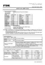
Specifikace & informace pro objednání
| Produkt | Supply voltage AC | Supply voltage DC | Popis | |
|---|---|---|---|---|
|
|
100-240 V | Motor Condition Monitoring, AC, 3-phase, Induction motor, Current Analysis model, 100 to 240 VAC, Transistor control output, Push-in Plus, LCD display, Ethernet IP/Modus, applicable in environment with inverters |
|
|
|
|
20.4-26.4 V | 20.4-26.4 V | Motor Condition Monitoring, AC, 3-phase, Induction motor, Current Analysis model, 24 VAC/VDC, Transistor control output, Push-in Plus, LCD display, Ethernet IP/Modbus, applicable in environment with inverters |
|
Potřebujete pomoc?
Jsme zde, abychom vám pomohli! Kontaktujte nás a naši specialisté vám pomohou najít nejlepší řešení pro vaše podnikání.
Kontaktujte nás K6CM-CI2M
Děkujeme Vám za odeslání vašeho požádavku. Budeme Vás kontaktovat co nejdříve.
Objevili se technické potíže. Odeslání Vašeho formuláře nebylo úspěšné. Prosím přijměte naši omluvu a zkuste to znovu později. Podrobnosti: [detaily]
Nabídka pro K6CM-CI2M
Vyplněním tohoto formuláře můžete požádat o cenovou nabídku vybraného produktu. Prosím vyplňte všechna povinná pole označená *. S vašimi osobními údaji bude nakládáno důvěrně.
Děkujeme Vám za vaši žádost o cenovou nabídku. Požadované informace Vám poskytneme co nejdříve.
Objevili se technické potíže. Odeslání Vašeho formuláře nebylo úspěšné. Prosím přijměte naši omluvu a zkuste to znovu později. Podrobnosti: [detaily]
Feature
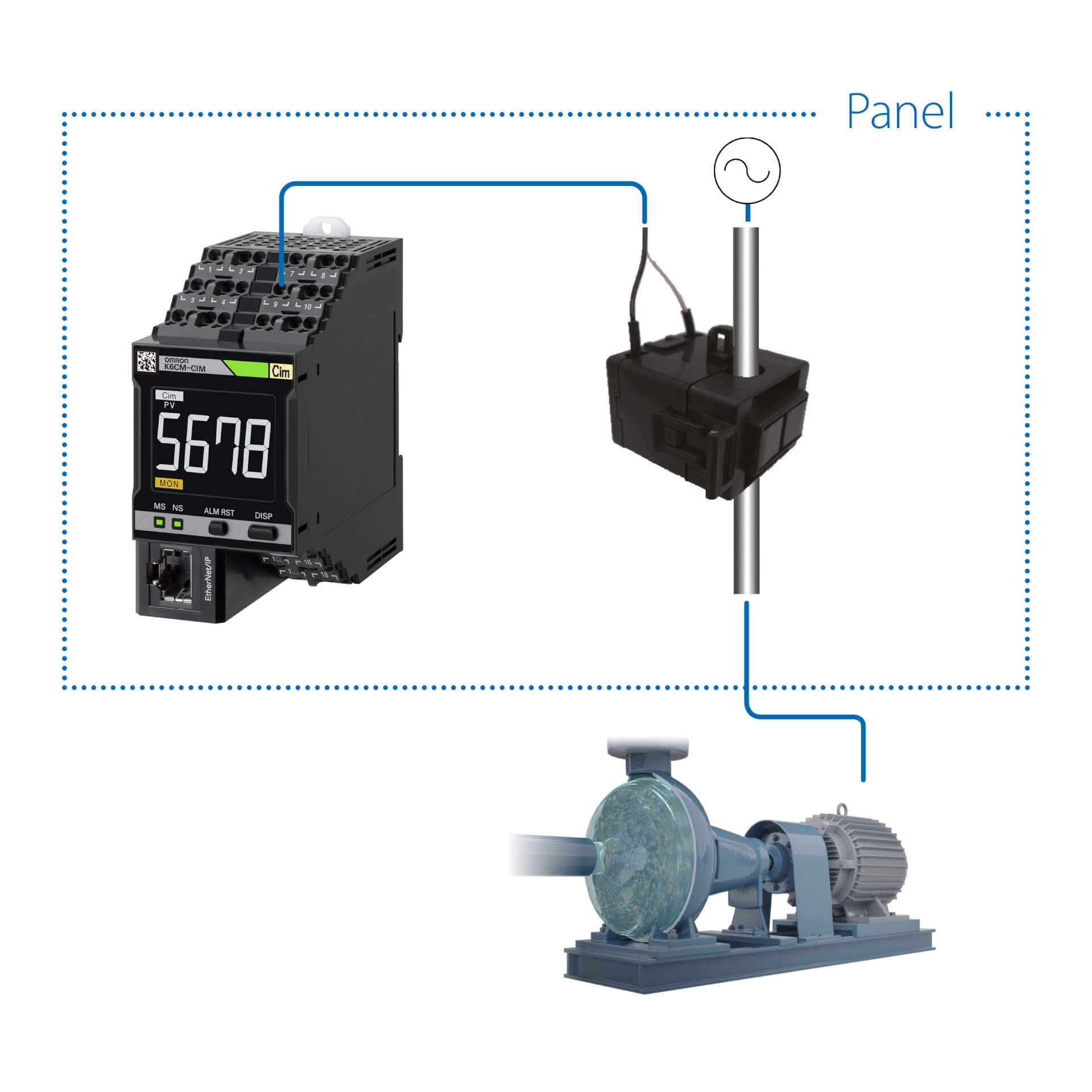
Model K6CM-CI2M lze snadno instalovat do stávajících strojů, protože není třeba zajišťovat kabeláž pro motor/čerpadlo.
Řídicí jednotka a proudový transformátor jsou umístěny v rozváděči.
Zařízení pro monitorování stavu lze konfigurovat pomocí jediného nástroje
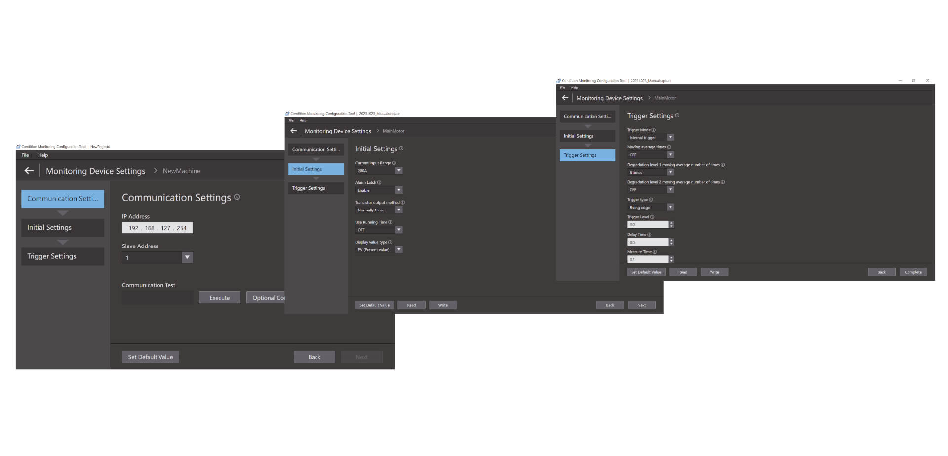
Snadná konfigurace ve třech krocích Nástroj pro konfiguraci monitorování stavu umožňuje hromadnou konfiguraci širokého spektra zařízení pro monitorování stavu, například zařízení pro monitorování motorů, teplot, izolace a topných těles. Lze jej používat bez speciálních dovedností, což snižuje nároky na školení.
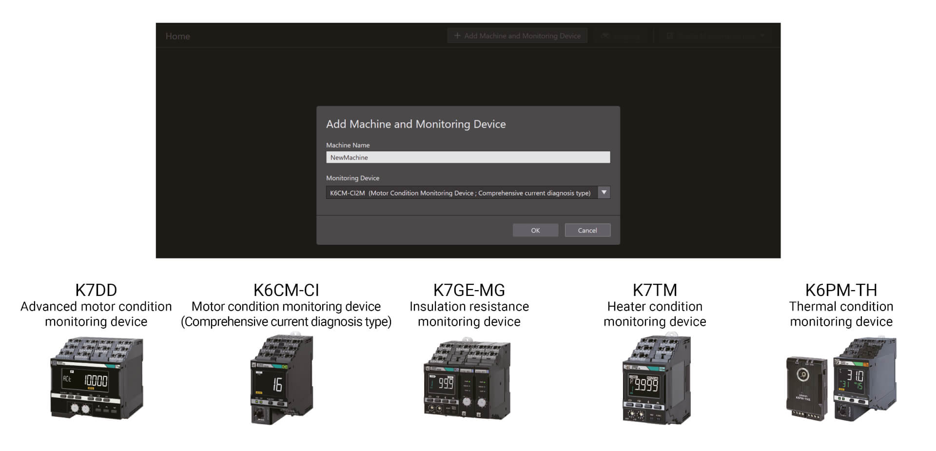
Snadná konfigurace ve třech krocích
Nástroj pro konfiguraci monitorování stavu umožňuje hromadnou konfiguraci širokého spektra zařízení pro monitorování stavu, například zařízení pro monitorování motorů, teplot, izolace a topných těles. Lze jej používat bez speciálních dovedností, což snižuje nároky na školení. Nastavení lze provést v pouhých třech krocích: nastavení komunikace, počáteční nastavení a nastavení spouštění.*1 Díky své vysoké operativnosti nástroj zvyšuje také produktivitu na pracovišti.
Videa

-
K6CM Motor Condition Monitoring Device
K6CM takes the burden of monitoring motors off maintenance engineers. Motors can be maintained in advance of failure due to deterioration. K6CM (comprehensive current diagnosis type) can consistently monitor motor conditions by observing the current waveform of the motor. Additionally, you can understand the motor's maintenance timing without depending on an engineer, because K6CM provides threshold value setting.
02:40
K6CM Motor Condition Monitoring Device
K6CM takes the burden of monitoring motors off maintenance engineers. Motors can be maintained in advance of failure due to deterioration. K6CM (comprehensive current diagnosis type) can consistently monitor motor conditions by observing the current waveform of the motor. Additionally, you can understand the motor's maintenance timing without depending on an engineer, because K6CM provides threshold value setting.
-

K6CM Demo Video
05:48
K6CM Demo Video


OMRON K6CM Conveyor Chain Demonstration Video


OMRON K6CM Misaligned Drive Belts Demonstration Video

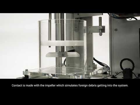
OMRON K6CM Mixer Demonstration Video


OMRON K6CM Pump Cavitation Demonstration Video


OMRON K6CM Spray Dryer Demonstration Video
Řešení
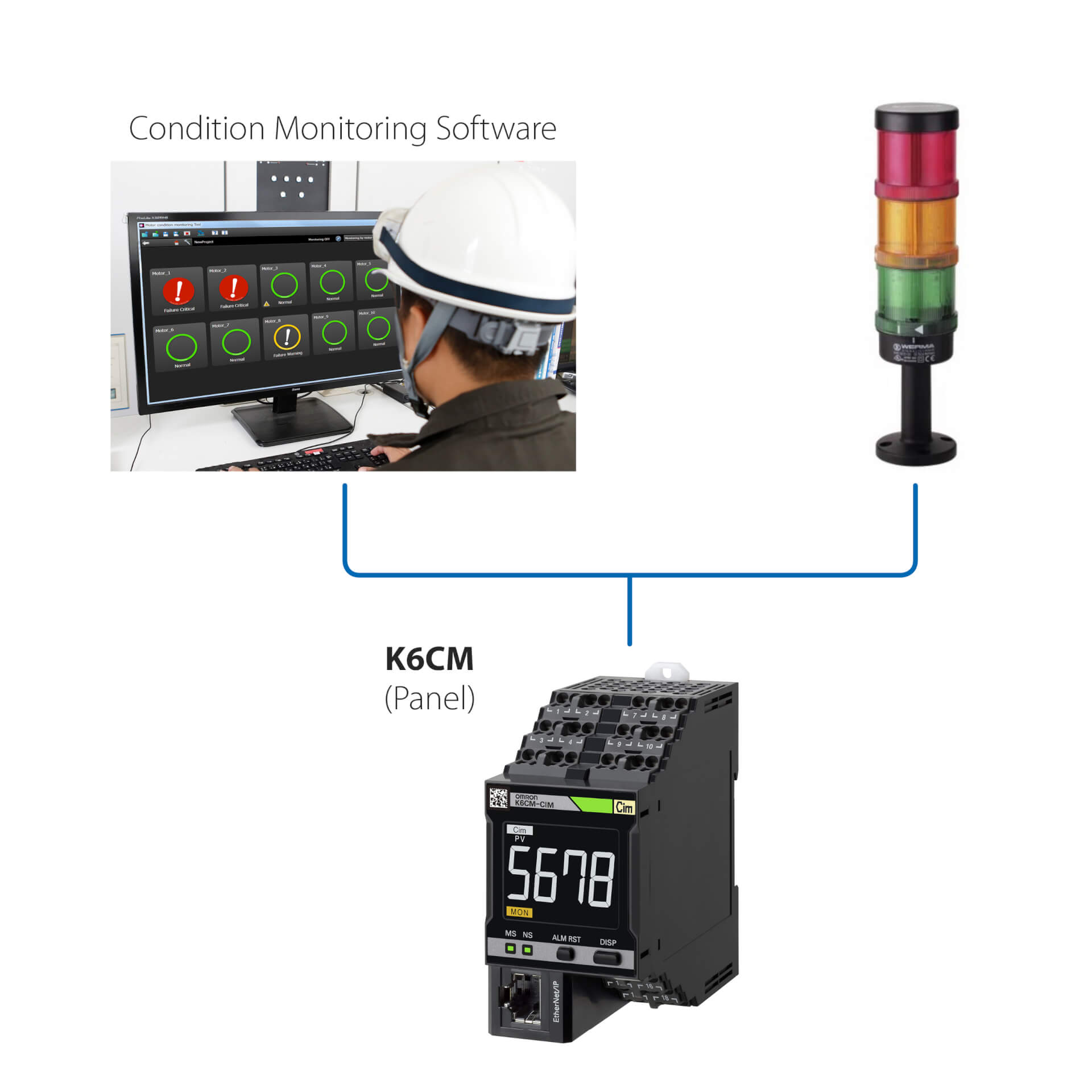
Samostatná instalace (bez jednotky PLC)
Toto jednoduché řešení umožňuje:
- Monitorovat stav motoru prostřednictvím integrované kontrolky LED nebo softwaru pro monitorování stavu
- Nastavit řídicí jednotky pomocí softwaru pro monitorování stavu dodaného se zařízením
- Propojit model K6CM s libovolnými externími vstupními/výstupními zařízeními (dig. výstup)
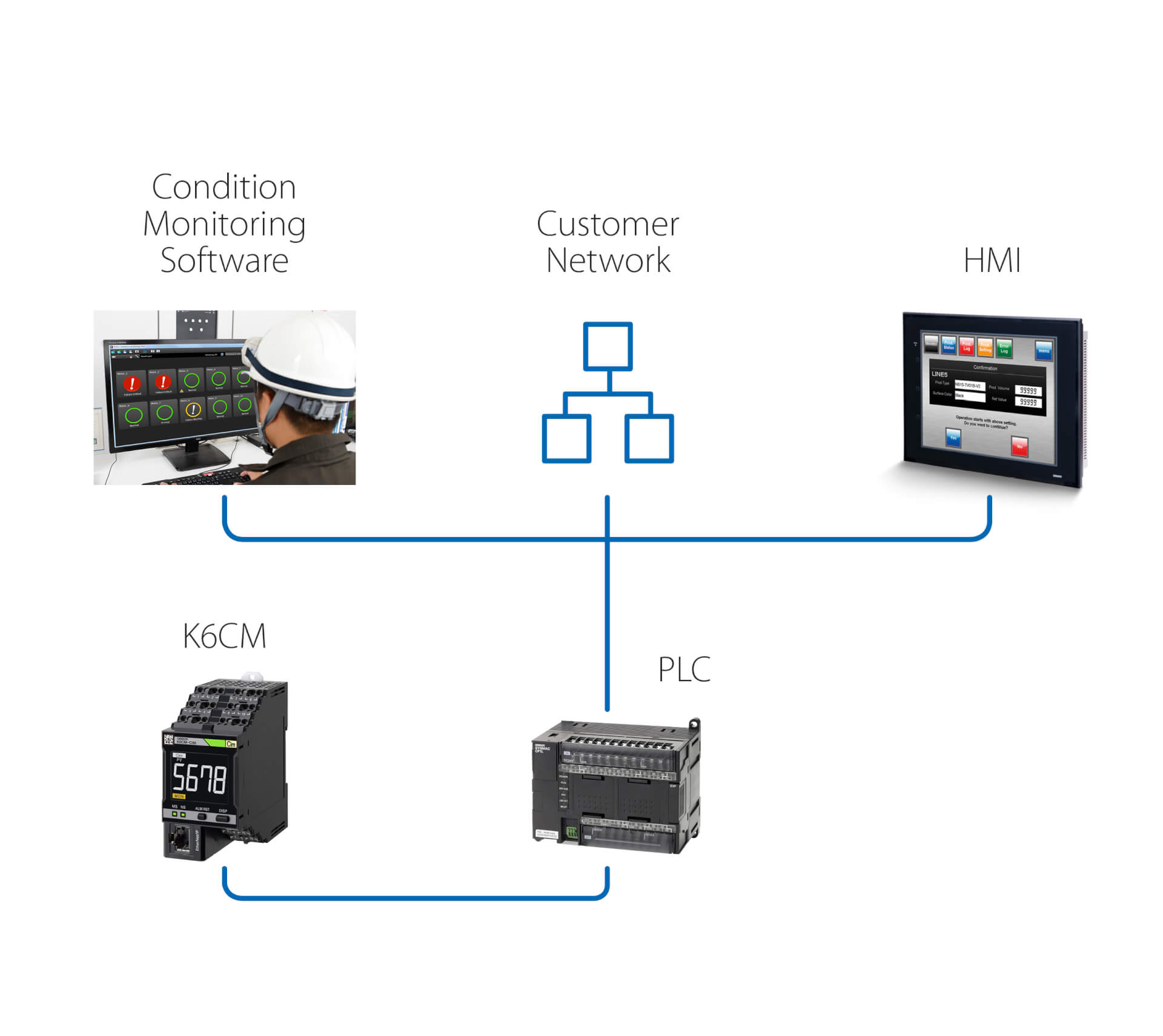
Samostatná instalace (s jednotkou PLC)
Toto řešení navíc k předchozímu řešení umožňuje:
- Monitorovat stav motoru prostřednictvím softwaru pro monitorování stavu, který běží na počítači připojeném přes jednotku PLC
- Prostřednictvím jednotky PLC aktivovat akce následující po jakékoli výstraze/alarmu, které detekuje model K6CM
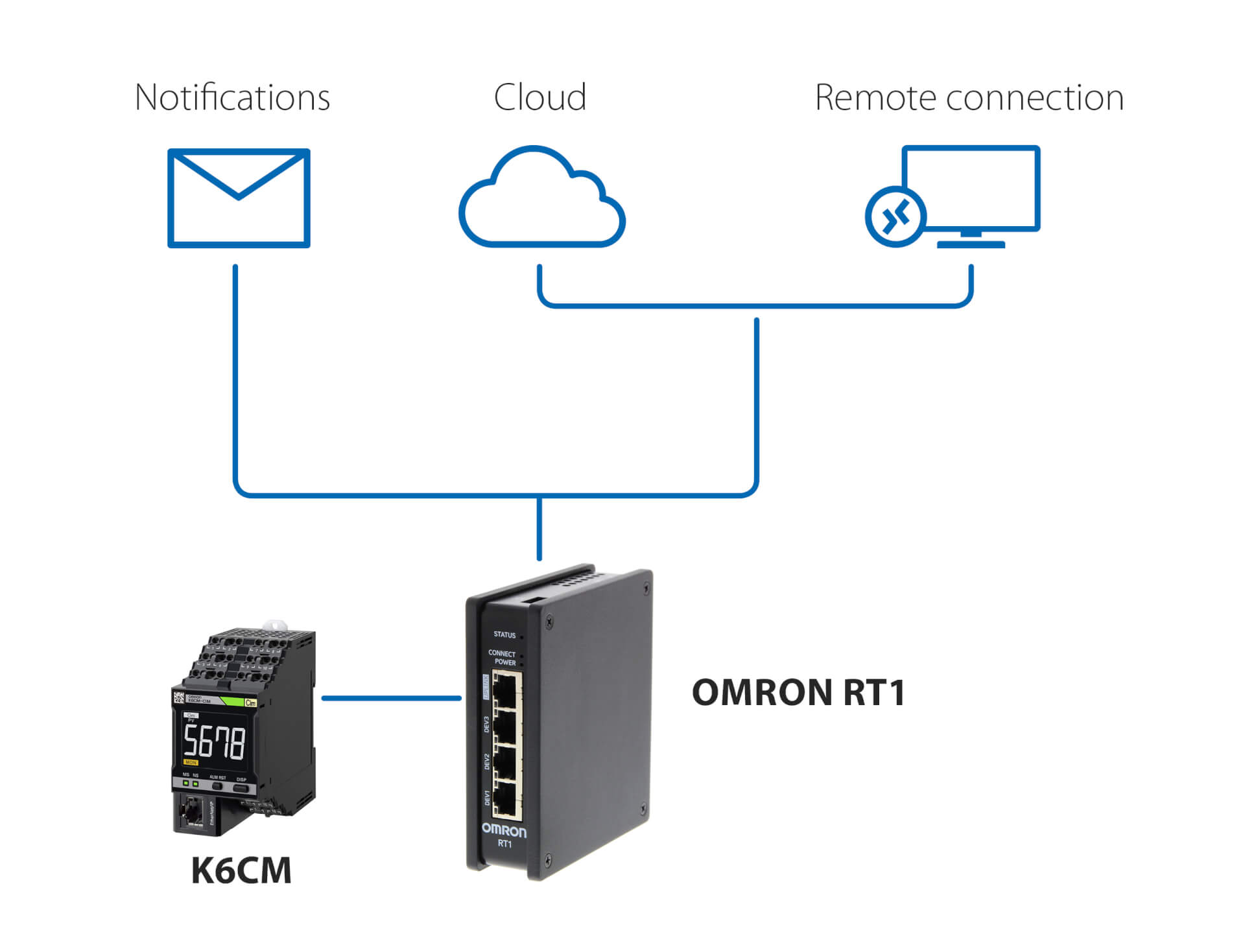
Oznámení a vzdálené monitorování – bez jednotky PLC
Toto řešení, které využívá OMRON RT1 jako bránu, umožňuje:
- zasílání oznámení e-mailem / zprávou SMS v případě, že model K6CM zjistí anomálie
- zabezpečené připojení (spravované ze strany RT1) do cloudu, buď prostřednictvím sítě LAN, nebo prostřednictvím připojení 4G
- zabezpečené připojení pro vzdálené monitorování a nastavení modelu K6CM pomocí softwaru pro monitorování stavu dodaného s řídicí jednotkou
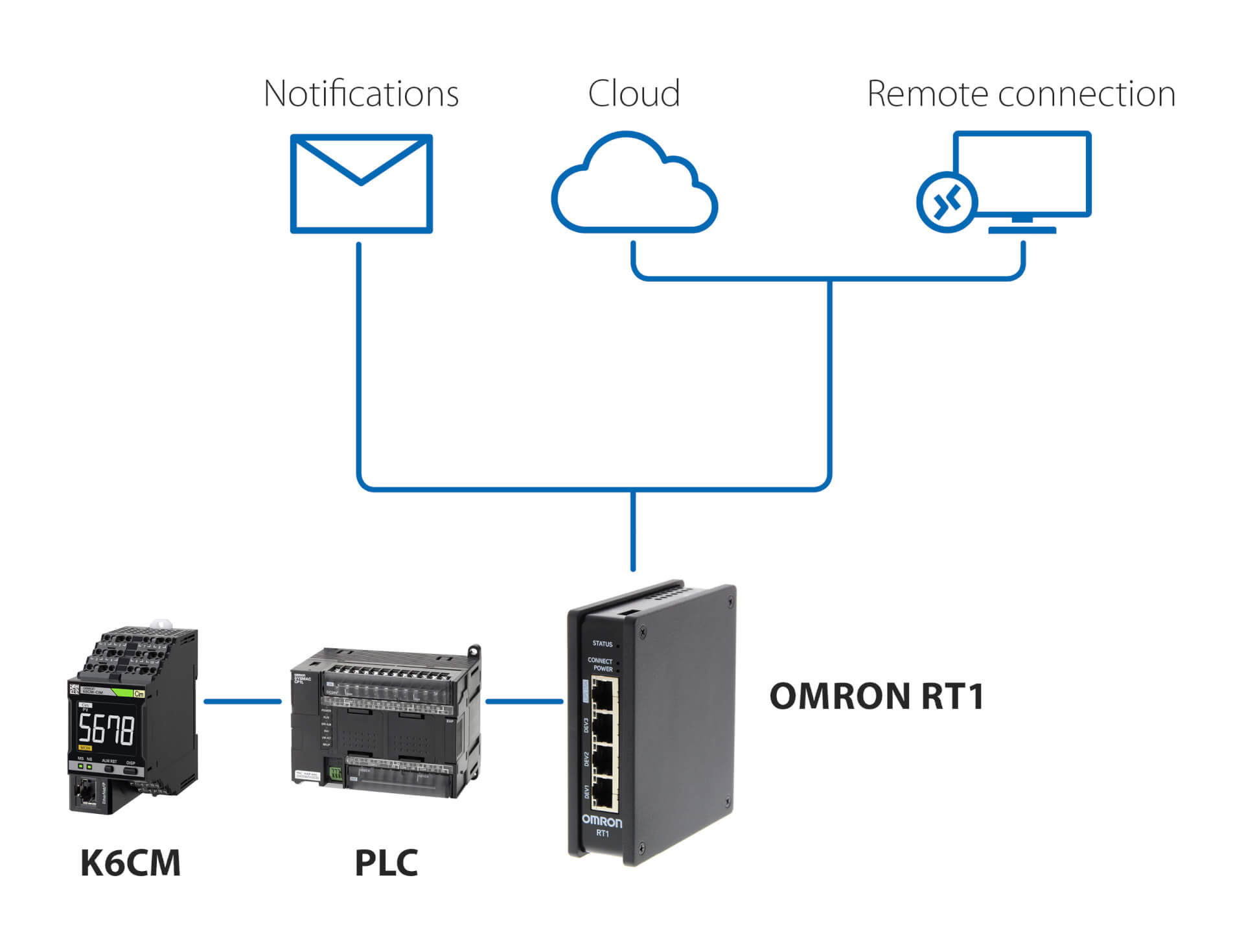
Oznámení a vzdálené monitorování – s jednotkou PLC
Toto řešení, které využívá všechny jednotky PLC a OMRON RT1 jako bránu, umožňuje:
- zasílání oznámení e-mailem / zprávou SMS v případě, že model K6CM zjistí anomálie
- zabezpečené připojení (spravované ze strany RT1) do cloudu, buď prostřednictvím sítě LAN, nebo prostřednictvím připojení 4G
- zabezpečené připojení pro vzdálené monitorování a nastavení modelu K6CM pomocí softwaru pro monitorování stavu dodaného s řídicí jednotkou
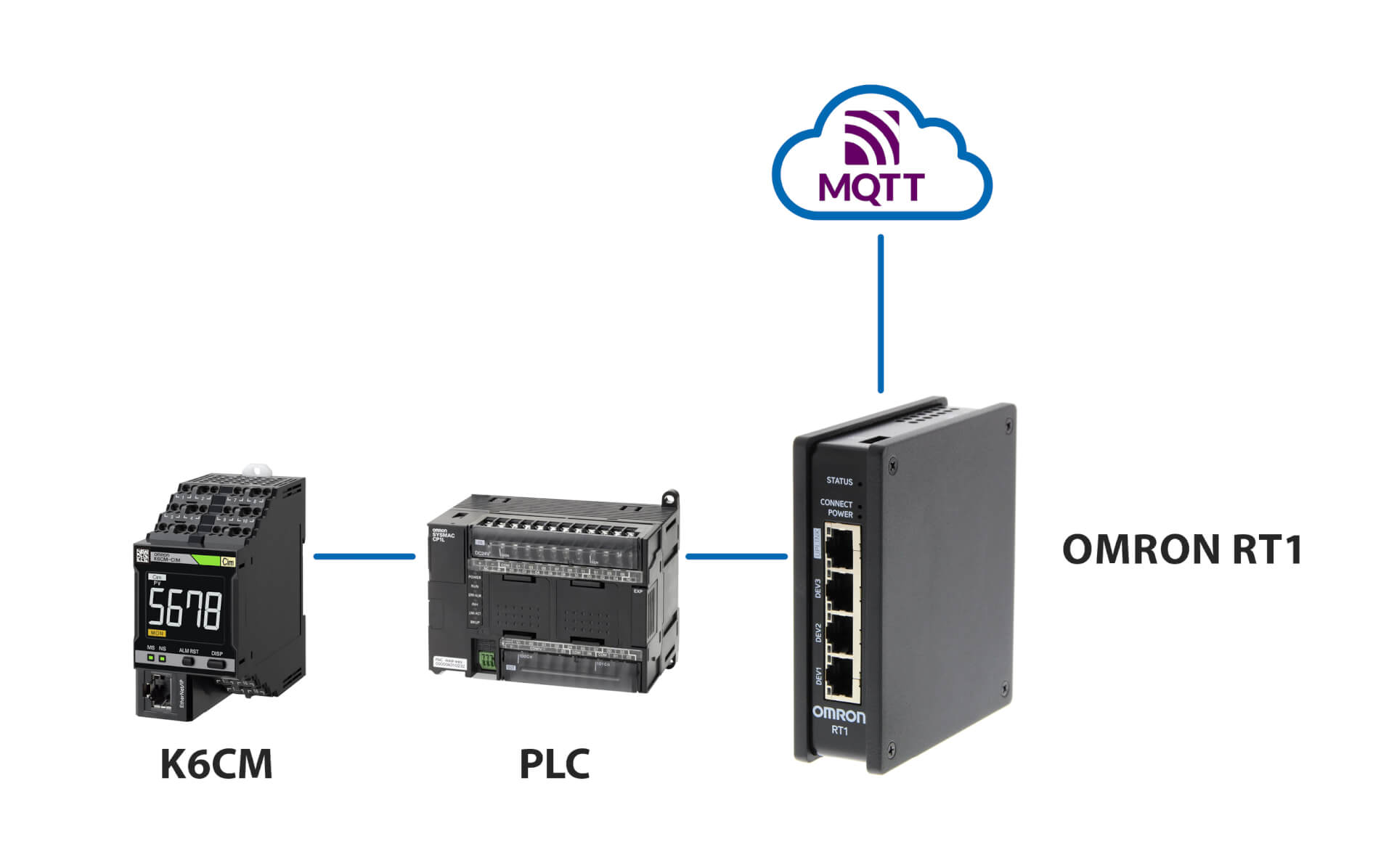
Připojení k serveru MQTT
Související produkty
-
Zařízení pro monitorování stavu motoru – monitorování izolace
-
Zařízení pro monitorování stavu motoru – monitorování vibrací
-
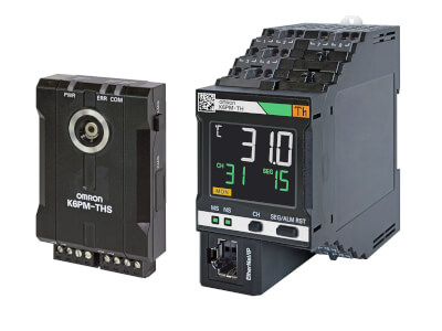
Monitorování stavu na základě termografie
-
Zařízení pro monitorování stavu – monitorování izolace
Stahování dokumentace