MY
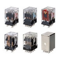
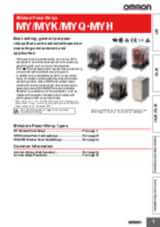
Řada univerzálních relé vhodných pro různá prostředí a aplikace
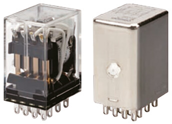
- Do standardního vybavení všech modelů* řady produktů MY patří průhledný kryt, mechanický indikátor, který umožňuje snadno zkontrolovat stav kontaktů, a kontrolka LED – nejen pro indikaci správného fungování relé, ale také k okamžité identifikaci typu napětí cívky: červená LED pro střídavou cívku a zelená LED pro stejnosměrnou cívku.
- Vývody o šířce 2,6 mm, které nabízejí vyšší vodivost a menší nárůst teploty.
- MY-GS-R je hvězdou řady s 2pólovými a 4pólovými modely s kontrolkou LED, testovacím tlačítkem a ochranou. Stejnosměrná verze nemá díky provedení s LED polaritu (bez modelů s diodou).
- K dispozici jsou hermeticky uzavřená nebo zatavená relé, modely s rozdvojenými pozlacenými kontakty pro malé zatížení.
- Dobu zapojení lze zkrátit až o 60 %** v porovnání s tradičními paticemi se šroubovými svorkami. Díky kombinaci řešení MY s paticemi se svorkami Push-in Plus (PYF-[]-PU) dovoluje menší potřebná síla pro zasunutí zkrátit dobu zapojení.
* Bez speciálních modelů
** Když se patice se svorkami Push-in Plus a patice se šroubovými svorkami zkombinují s typy zásuvných svorkovnic
Ukončení výroby produktu: Březen 2024 platí POUZE pro EVROPU. Stáhněte si toto oznámení o ukončení výroby, kde naleznete další informace.
Specifikace & informace pro objednání
| Produkt | Mounting method | Usage | Poles | Rated carry current | Coil voltage | Operation voltage | Contact material | Contact description | Features | Terminal type | Popis | |
|---|---|---|---|---|---|---|---|---|---|---|---|---|
|
|
With plug-in socket | General purpose | 2 | 10 A | 110 V | AC | Ag | DPDT | Transparent case, With mechanical indicator | Plug-in, Solder | Relay, plug-in, 8-pin, DPDT, 10 A, mechanical indicator, 110/120 VAC (20260409) |
|
|
|
With plug-in socket | General purpose | 2 | 10 A | 12 V | AC | Ag | DPDT | Transparent case, With mechanical indicator | Plug-in, Solder | Relay, plug-in, 8-pin, DPDT, 10 A, mechanical indicator, 12 VAC.... |
|
|
|
With plug-in socket | General purpose | 2 | 10 A | 230 V | AC | Ag | DPDT | Transparent case, With mechanical indicator | Plug-in, Solder | Relay, plug-in, 8-pin, DPDT, 10 A, mechanical indicator, 220/240 VAC |
|
|
|
With plug-in socket | General purpose | 2 | 10 A | 24 V | AC | Ag | DPDT | Transparent case, With mechanical indicator | Plug-in, Solder | Relay, plug-in, 8-pin, DPDT, 10 A, mechanical indicator, 24 VAC |
|
|
|
With plug-in socket | General purpose | 2 | 10 A | 48 V | AC | Ag | DPDT | Transparent case, With mechanical indicator | Plug-in, Solder | Relay, plug-in, 8-pin, DPDT, 10 A, mechanical indicator, 48 VAC |
|
|
|
With plug-in socket | General purpose | 2 | 10 A | 110 V | DC | Ag | DPDT | Transparent case, With mechanical indicator | Plug-in, Solder | Relay, plug-in, 8-pin, DPDT, 10 A, mechanical indicator, 100/110 VDC |
|
|
|
With plug-in socket | General purpose | 2 | 10 A | 12 V | DC | Ag | DPDT | Transparent case, With mechanical indicator | Plug-in, Solder | Relay, plug-in, 8-pin, DPDT, 10 A, mechanical indicator, 12 VDC |
|
|
|
With plug-in socket | General purpose | 2 | 10 A | 24 V | DC | Ag | DPDT | Transparent case, With mechanical indicator | Plug-in, Solder | Relay, plug-in, 8-pin, DPDT, 10 A, mechanical indicator, 24 VDC |
|
|
|
With plug-in socket | General purpose | 2 | 10 A | 48 V | DC | Ag | DPDT | Transparent case, With mechanical indicator | Plug-in, Solder | Relay, plug-in, 8-pin, DPDT, 10 A, mechanical indicator, 48 VDC |
|
|
|
With plug-in socket | General purpose | 2 | 10 A | 110 V | AC | Ag | DPDT | CR circuit, LED, Test button, Transparent case, With mechanical indicator | Plug-in, Solder | Relay, plug-in, 8-pin, DPDT, 10 A, mechanical & LED indicators, Coil Surge Absorption, lockable push test button, 110/120 VAC |
|
|
|
With plug-in socket | General purpose | 2 | 10 A | 230 V | AC | Ag | DPDT | CR circuit, LED, Test button, Transparent case, With mechanical indicator | Plug-in, Solder | Relay, plug-in, 8-pin, DPDT, 10 A, mechanical & LED indicators, Coil Surge Absorption, lockable push test button, 220/240 VAC |
|
|
|
With plug-in socket | General purpose | 2 | 10 A | 24 V | DC | Ag | DPDT | Diode, LED, Test button, Transparent case, With mechanical indicator | Plug-in | Relay, plug-in, 8-pin, DPDT, 10 A, mechanical & LED indicators, with built-in diode for coil surge absorption, reverse polarity, lockable push test button, 24 VDC |
|
|
|
With plug-in socket | General purpose | 2 | 10 A | 110 V | DC | Ag | DPDT | Diode, LED, Test button, Transparent case, With mechanical indicator | Plug-in, Solder | Relay, plug-in, 8-pin, DPDT, 10 A, mechanical & LED indicators, Coil Surge Absorption, lockable push test button, 100/110 VDC |
|
|
|
With plug-in socket | General purpose | 2 | 10 A | 12 V | DC | Ag | DPDT | Diode, LED, Test button, Transparent case, With mechanical indicator | Plug-in, Solder | Relay, plug-in, 8-pin, DPDT, 10 A, mechanical & LED indicators, Coil Surge Absorption, lockable push test button, 12 VDC |
|
|
|
With plug-in socket | General purpose | 2 | 10 A | 24 V | DC | Ag | DPDT | Diode, LED, Test button, Transparent case, With mechanical indicator | Plug-in, Solder | Relay, plug-in, 8-pin, DPDT, 10 A, mechanical & LED indicators, Coil Surge Absorption, lockable push test button, 24 VDC |
|
|
|
With plug-in socket | General purpose | 2 | 10 A | 110 V | AC | Ag | DPDT | LED, Test button, Transparent case, With mechanical indicator | Plug-in, Solder | Relay, plug-in, 8-pin, DPDT, 10 A, mechanical & LED indicators, lockable push test button, 110/120 VAC |
|
|
|
With plug-in socket | General purpose | 2 | 10 A | 12 V | AC | Ag | DPDT | LED, Test button, Transparent case, With mechanical indicator | Plug-in, Solder | Relay, plug-in, 8-pin, DPDT, 10 A, mechanical & LED indicators, lockable push test button, 12 VAC |
|
|
|
With plug-in socket | General purpose | 2 | 10 A | 230 V | AC | Ag | DPDT | LED, Test button, Transparent case, With mechanical indicator | Plug-in, Solder | Relay, plug-in, 8-pin, DPDT, 10 A, mechanical & LED indicators, lockable push test button, 220/240 VAC |
|
|
|
With plug-in socket | General purpose | 2 | 10 A | 24 V | AC | Ag | DPDT | LED, Test button, Transparent case, With mechanical indicator | Plug-in, Solder | Relay, plug-in, 8-pin, DPDT, 10 A, mechanical & LED indicators, lockable push test button, 24 VAC |
|
|
|
With plug-in socket | General purpose | 2 | 10 A | 48 V | AC | Ag | DPDT | LED, Test button, Transparent case, With mechanical indicator | Plug-in, Solder | Relay, plug-in, 8-pin, DPDT, 10 A, mechanical & LED indicators, lockable push test button, 48 VAC |
|
Potřebujete pomoc?
Jsme zde, abychom vám pomohli! Kontaktujte nás a naši specialisté vám pomohou najít nejlepší řešení pro vaše podnikání.
Kontaktujte nás MY

Děkujeme Vám za odeslání vašeho požádavku. Budeme Vás kontaktovat co nejdříve.
Objevili se technické potíže. Odeslání Vašeho formuláře nebylo úspěšné. Prosím přijměte naši omluvu a zkuste to znovu později. Podrobnosti: [detaily]
Nabídka pro MY
Vyplněním tohoto formuláře můžete požádat o cenovou nabídku vybraného produktu. Prosím vyplňte všechna povinná pole označená *. S vašimi osobními údaji bude nakládáno důvěrně.
Děkujeme Vám za vaši žádost o cenovou nabídku. Požadované informace Vám poskytneme co nejdříve.
Objevili se technické potíže. Odeslání Vašeho formuláře nebylo úspěšné. Prosím přijměte naši omluvu a zkuste to znovu později. Podrobnosti: [detaily]
Modely
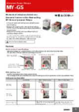
MY-GS-R - Miniature Power Relays Mechanical indicators added as a standard feature to our best-selling MY General-purpose relays
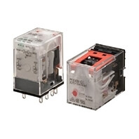
- MY-GS-R – poslední přírůstek do rodiny produktů MY: vyrobený v plně automatizované továrně.
- Zkracuje zapojení o 60 % při zkombinování s paticí Push-In Plus PYF-PU (podle skutečných měření společnosti OMRON).
- Tisk na cívkovou pásku indikuje specifikaci provozní cívky.
- Mechanické indikátory provozu jsou standardní funkcí u všech modelů.
- Vyhovuje směrnicím RoHS, UL, CSA a IEC (certifikace VDE).
- Mechanické indikátory jsou standardní funkcí u všech modelů, aby bylo možné snadno kontrolovat stav kontaktů.
- Model MY-GS-R je vhodný pro použití tam, kde je potřeba spolehlivé relé. Se standardním modelem se lze často setkat u balicích strojů v potravinářském a nápojovém průmyslu.
MY(S) - Miniature Power Relays
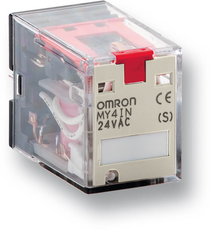
Všestranné zásuvné relé, které stanovuje normy
- Od svého představení již byla vyrobena více než 1 miliarda kusů tohoto miniaturního výkonového relé, které se využívá v mnoha různých oblastech. Rozdvojené kontakty jsou volitelně k dispozici pro dosažení spolehlivého přepínání nízkého proudu během celého elektrického životního cyklu. Celá řada patic od montáže pomocí šroubu přes zapouzdřenou svorkovnici až po pružné svorky.
- Modely MY-S, které zahrnují LED a testovací tlačítko, se staly nejprodávanějšími produkty zásluhou viditelného indikátoru a snadno použitelné testovací funkce.
- Řada MY-S zahrnuje modely MY4Z s rozdvojenými kontakty pro drobná zatížení.
- MY-S se běžně využívá v odvětví automatizace výstavby, kde si ho zákazníci často vybírají jako preferované relé pro systémy řízení klimatu / vytápění, větrání, klimatizace a výtahů.
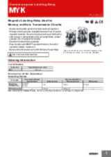
MYK - Miniature Power Latching Relays
Magnetické relé s přidržením ideální pro obvody s přenosem dat a paměti
- Magnetické relé s přidržením MYK, které si udržuje stav kontaktního provozu a vyznačuje se nízkou spotřebou energie.
- Systém dvojitých svorek, který si udržuje zbytkový magnetismus. Díky speciálním magnetickým materiálům jsou změny způsobené stárnutím jen zanedbatelné, což zaručuje dlouhou výdrž. Během dlouhé životnosti dochází jen k drobným změnám charakteristik, jako jsou souběh kontaktů, tlak na kontakty atd.
- Vynikající odolnost proti otřesům/vibracím.
- Integrovaný provozní indikátor zaručuje snadné monitorování provozu zapínání/vypínání.
- MY2K se používá také v rozváděčích vyhrazených pro použití ve větrných elektrárnách.
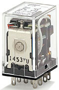
MYQ/MYH - Miniature Power Sealed Relays
Utěsněná relé pro použití v náročných prostředích, kde se vyskytuje prach, žíravé plyny atd.
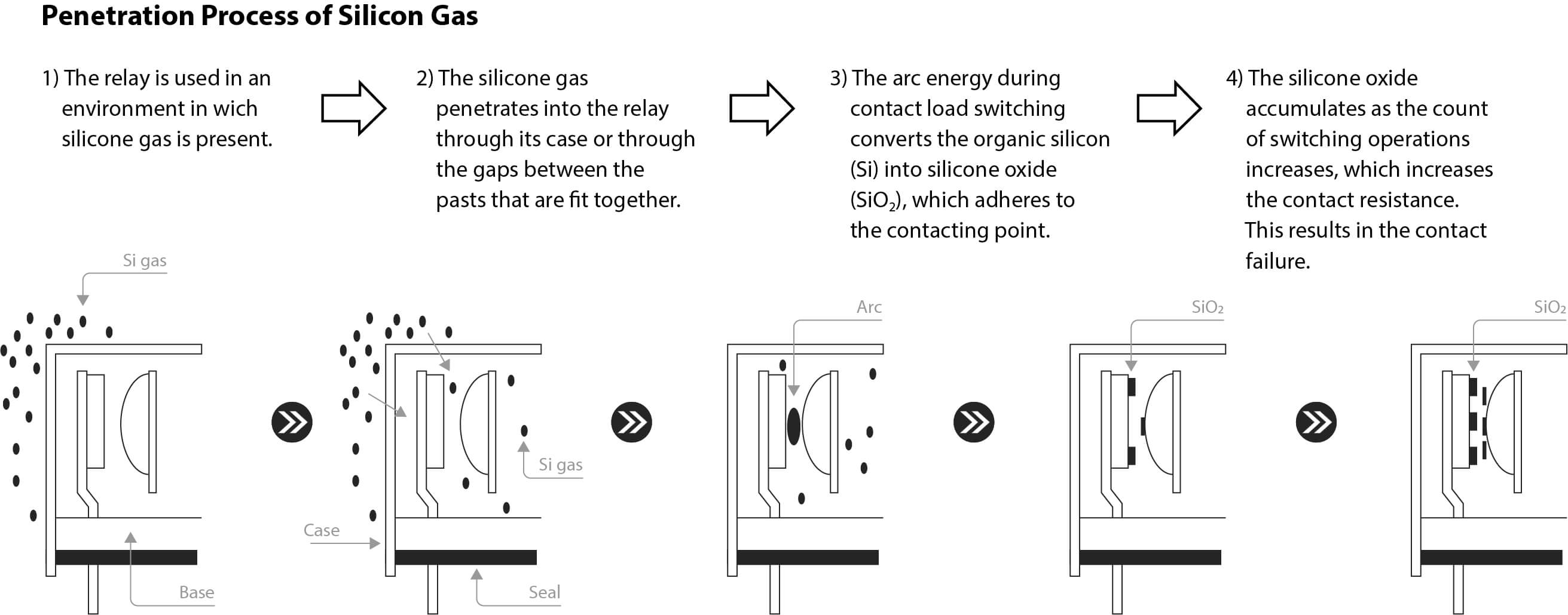
- V prostředích, kde se vytváří velké množství prachu, například u vstřikovacích strojů a brusek, nebo v prostředích s výskytem drobného hmyzu (jako jsou komáři či moskyti) hrozí, že by tyto cizí substance mohly proniknout do relé mezerami mezi jednotlivými součástmi nebo větracími otvory relé. Jakmile se prach či hmyz do relé dostanou, většinou v něm i zůstanou. Pokud se přilepí na kontakty, může dojít k potížím s poruchami kontaktů nebo nestabilními kontakty. Plastová utěsněná relé (MYQ) a hermeticky utěsněná relé (MYH) jsou odolná proti účinkům okolního prostředí.
- Doporučeno rovněž pro prostředí, kde dochází k tvorbě žíravých plynů, jako jsou chlorné, sirné a silikonové plyny.
- Odolají dokonce i prostředím, kde dochází k poškození ze strany soli a generování prachu.
- Brání selháním kontaktů relé pomocí vzduchotěsné konstrukce.
Videa

-

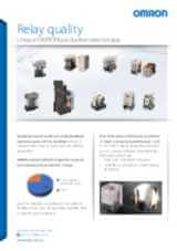
OMRON Relay Quality
Creating the perfect relays may seem like a straightforward task, but it’s a complex process that requires the most advanced manufacturing processes. This ensures that every component inside our relays are precisely assembled and protected from any outside contaminants. Ignoring this crucial step could jeopardize the reliability of the relays and compromise their switching activity. At times, machines can experience unplanned downtime, with the causes remaining elusive, in many cases restarting the machine or replacing the relays resolves the issue. OMRON determined that such incidents are primarily caused by inadequate contact conduction, which frequently results from dust caught between the contacts during manufacturing. OMRON's unique production techniques avoid poor conduction due to dust by providing standardized product design, producing the products in clean room with strict entry/exit control rules, and utilizing OMRON’s unique dust removal technology. This production technique are applied for all the OMRON relays especially the new ones introduced in the line up G2RV-ST/G3RV-ST, and MY-GS-R. Find out more about our new relays in our website: #MakeitOMRON #MakeitExcellent
02:30
OMRON Relay Quality
Creating the perfect relays may seem like a straightforward task, but it’s a complex process that requires the most advanced manufacturing processes. This ensures that every component inside our relays are precisely assembled and protected from any outside contaminants. Ignoring this crucial step could jeopardize the reliability of the relays and compromise their switching activity. At times, machines can experience unplanned downtime, with the causes remaining elusive, in many cases restarting the machine or replacing the relays resolves the issue. OMRON determined that such incidents are primarily caused by inadequate contact conduction, which frequently results from dust caught between the contacts during manufacturing. OMRON's unique production techniques avoid poor conduction due to dust by providing standardized product design, producing the products in clean room with strict entry/exit control rules, and utilizing OMRON’s unique dust removal technology. This production technique are applied for all the OMRON relays especially the new ones introduced in the line up G2RV-ST/G3RV-ST, and MY-GS-R. Find out more about our new relays in our website: #MakeitOMRON #MakeitExcellentSouvisející produkty
-
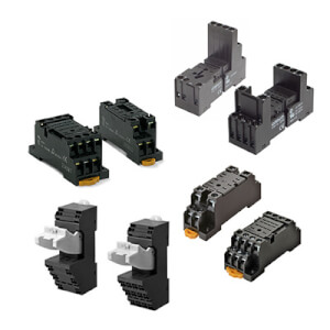
PYF jsou patice pro relé řady MY, vhodné i pro polovodičová relé (SSR) a časovače
Stahování dokumentace
_miniature_power_relays_datasheet_en.jpg)
_series_(europe)_discontinuation_notice_en.jpg)
_discontinuation_notice_en.jpg)
_myk_myq_myh_miniature_power_relays_datasheet_en.jpg)
n1-d2_and_my4(i)n1-d2_discontinuation_notice_en.jpg)