ZS-HL
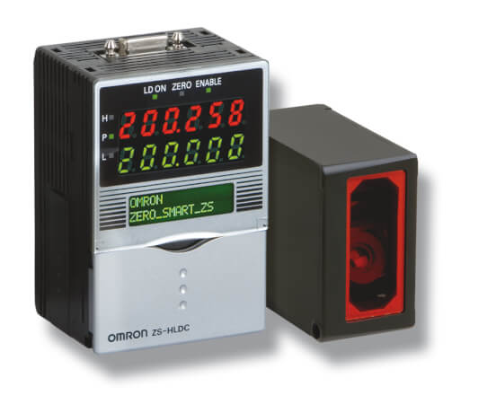
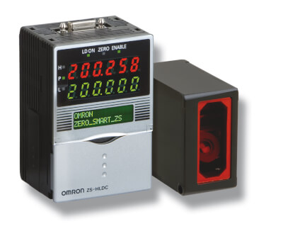
Rozšířitelný laserový měřicí senzor s vysokou přesností
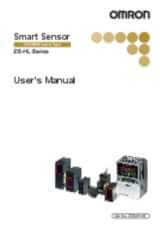
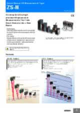
Inteligentní senzor ZS-HL nabízí vynikající dynamický snímací rozsah pro všechny povrchy od černé gumy až po skleněné i zrcadlové povrchy, který lze jednoduše přizpůsobovat vlastním potřebám. Verze ZS-HL je rozšířená varianta verze ZS-L, která je vhodná pro dlouhé měřicí dosahy, a poskytuje zpětnou kompatibilitu se snímacími hlavicemi a příslušenstvím.
- Nejvyšší rozlišení a dynamický snímací rozsah pro všechny povrchy
- Koncepce modulární a rozšiřitelné platformy použitelné až pro 9 senzorů
- Snadné použití, instalace a údržba pro uživatele na všech úrovních
- Rychlá doba odezvy 110 µs
- Funkce víceúlohového zpracování dokáže řídit 4 měřicí nástroje v jedné řídicí jednotce
Specifikace & informace pro objednání
Ordering information
Sensors
ZS-HL-series sensor heads
|
Resolution1 |
|||||
|---|---|---|---|---|---|
ZS-HL-series sensor heads (for nozzle gaps) also compatible with ZS-L controller
|
Resolution2 |
|||||
|---|---|---|---|---|---|
ZS-L-series sensor heads
|
Resolution3 |
|||||
|---|---|---|---|---|---|
ZS-HL-series sensor controllers
Multi-controllers
Data storage units
Accessories (sold separately)
Controller link
Panel mount adapter
Cables for connecting to a Personal Computer
Extension cables for sensor heads
|
ZS-XC10B1 |
Logging software
Memory card
Safety precautions for using laser equipment

Specifications
Sensor heads
ZS-HL-series sensor heads
|
Visible semiconductor laser (wavelength: 650 nm, 1 mW max., JIS Clas |
Visible semiconductor laser (wavelength 658 nm, 1 mW max., Class 2) |
|||||||||
|
Beam diameter1 |
||||||||||
|
Linearity2 |
||||||||||
|
Resolution3 |
||||||||||
|
Temperature characteristic4 |
||||||||||
|
110 µs (high-speed mode), 500 µs (standard mode), 2.2 ms (high-precision mode), 4.4 ms (high-sensitivity mode) |
||||||||||
|
Lits near the measurement center, and nearer than the measurement center distance inside the measuring range. |
||||||||||
|
Lits near the measurement center, and further than the measurement center distance inside the measuring range. |
||||||||||
|
Illumination on received light surface 3,000 lx or less (incandescent light) |
Illumination on received light surface 1,000 lx or less (incandescent light) |
Illumination on received light surface 500 lx or less (incandescent light) |
||||||||
|
Operating: 0 to 50°C, storage: -15 to 60°C (with no icing or condensation) |
||||||||||
|
10 to 150 Hz, 0.7 mm double amplitude, 80 min each in X, Y, and Z directions |
||||||||||
|
150 m/s² 3 times each in six directions (up/down, left/right, forward/backward) |
||||||||||
*1 Defined as 1/e² (13.5%) of the center optical intensity in the measurement center distance. The beam diameter is sometimes influenced by the ambient conditions of the workpiece such as leaked light from the main beam.
*2 This is the error on the measured value with respect to an ideal straight line. Linear curve may change according to the workpiece. The following lists the workpieces
*3 This is the “peak-to-peak” displacement conversion value of the displacement output in the measurement center distance when high-resolution mode and the average number in the table are set (For ZS-HLDS60, the maximum resolution at 250 mm is also included). The following lists the workpieces.
*4 Value obtained when the sensor part and object part are fixed with an aluminum jig.
ZS-L-series sensor heads
|
Visible semiconductor laser (wavelength: 650 nm, 1 mW max., JIS Class 2) |
|||||||||
|
Beam diameter6 |
|||||||||
|
Linearity7 |
|||||||||
|
Resolution8 |
|||||||||
|
Temperature characteristic9 |
|||||||||
|
Sampling cycle10 |
110 µs (high-speed mode), 500 µs (standard mode), 2.2 ms (high-precision mode), 4.4 ms (high-sensitivity mode) |
||||||||
|
Lights near the measuring center distance, and nearer than the measuring center distance inside the measuring range. Flashes when the measurement target is outside of the measuring range or when the received light amount is insufficient. |
|||||||||
|
Lights near the measuring center distance, and further than the measuring center distance inside the measuring range. Flashes when the measurement target is outside of the measuring range or when the received light amount is insufficient. |
|||||||||
|
Illumination on received light surface: 3,000 lx or less (incandescent light) |
|||||||||
|
Operating: 0 to 50°C, storage: -15 to 60°C (with no icing or condensation) |
|||||||||
|
Laser labels (1 each for JIS/EN, 3 for FDA), ferrite cores (2), insure Locks (2), instruction sheet |
Laser safety labels (1 each for JIS/EN),ferrite cores (2), insure locks (2) |
||||||||
ZS-L-series sensor heads
|
Visible semiconductor laser (wavelength: 650 nm, 1 mW max., JIS Class 2) |
||||||||||||
|
Beam diameter11 |
||||||||||||
|
Linearity12 |
||||||||||||
|
Resolution13 |
||||||||||||
|
Temperature characteristic14 |
||||||||||||
|
Sampling cycle15 |
110 µs (high-speed mode), 500 µs (standard mode), 2.2 ms (high-precision mode), 4.4 ms (high-sensitivity mode) |
|||||||||||
|
Lights near the measuring center distance, and nearer than the measuring center distance inside the measuring range. Flashes when the measurement target is outside of the measuring range or when the received light amount is insufficient. |
||||||||||||
|
Lights near the measuring center distance, and further than the measuring center distance inside the measuring range. Flashes when the measurement target is outside of the measuring range or when the received light amount is insufficient. |
||||||||||||
|
Illumination on received light surface: 3,000 lx or less (incandescent light) |
Illumination on received light surface: 2,000 lx or less (incandescent light) |
Illumination on received light surface: 3,000 lx or less (incandescent light) |
||||||||||
|
Operating: 0 to 50°C, storage: -15 to 60°C (with no icing or condensation) |
||||||||||||
|
Laser labels (1 each for JIS/EN, 3 for FDA), ferrite cores (2), insure Locks (2), instruction sheet |
||||||||||||
Sensor controllers
ZS-HL-series sensor controllers
ZS-MDC11/MDC41 multi controllers
Basic specifications are the same as those for the sensor controllers.
The following points, however, are different.
(1) Sensor heads cannot be connected.
(2) A maximum 9 of controllers can be connected. Control link units are required to connect controllers.
(3) Processing functions between controllers: Math functions
Controller link unit

Data storage units
|
10 controllers max. (ZS-MDC: 1 controller, ZS-HLDC: 9 controllers max.)16 |
||||
|
Serial I/O: connector, other: pre-wired (standard cable length: 2 m) |
||||
|
3 outputs: HIGH, PASS, and LOW
NPN open-collector, 30 VDC, 50 mA max., |
3 outputs: HIGH, PASS, and LOW
PNP open-collector, 50 mA max., |
|||
|
ON: Short-circuited to supply voltage or within 1.5 V of supply voltage |
||||
|
Start and stop triggers can be set separately; external triggers, data triggers (self-triggers), and time triggers |
||||
|
External banks, alarm outputs, saved data format customization, and clock |
||||
|
16 digitsx2 rows, color of characters: green, resolution per character: 5x8 pixel matrix |
||||
|
Direction keys (UP, DOWN, LEFT, and RIGHT), SET key, ESC key, MENU key, and function keys (1 to 4) |
||||
|
Threshold switch (2 states: High/Low), mode switch (3 states: FUN, TEACH, and RUN) |
||||
|
Operating: 0 to 50°C, storage: -15 to 60°C (with no icing or condensation) |
||||
|
Ferrite core (1) instruction sheet, tools for data storage unit: CSV file converter for data storage unit, smart analyzer macro edition |
||||
3. This is the peak-to-peak displacement conversion value in the displacement output at the measuring center distance in high-precision mode when the number of samples to average is set to 128 and the measuring mode is set to the high-resolution mode. The standard workpiece is white aluminum ceramics in diffuse reflection mode and glass in the regular reflection mode.
6. Defined as 1/e² (13.5%) of the center optical intensity at the actual measurement center distance (effective value). The beam diameter is sometimes influenced by the ambient conditions of the workpiece, such as leaked light from the main beam.
7. This is the error in the measured value with respect to an ideal straight line. The standard workpiece is white aluminum ceramics in diffuse reflection mode and glass in the regular reflection mode of the ZS-LD20T/40T/50. Linearity may change according to the workpiece.
8. This is the peak-to-peak displacement conversion value in the displacement output at the measuring center distance in high-precision mode when the number of samples to average is set to 128 and the measuring mode is set to the high-resolution mode. The standard workpiece is white aluminum ceramics in diffuse reflection mode and glass in the regular reflection mode.
9. This is the value obtained at the measuring center distance when the Sensor and workpiece are fixed by an aluminum jig.
11. Defined as 1/e² (13.5%) of the center optical intensity at the actual measurement center distance (effective value). The beam diameter is sometimes influenced by the ambient conditions of the workpiece, such as leaked light from the main beam.
12. This is the error in the measured value with respect to an ideal straight line. The standard workpiece is white aluminum ceramics in diffuse reflection mode and glass in the regular reflection mode of the ZS-LD20T/40T/50. Linearity may change according to the workpiece.
13. This is the peak-to-peak displacement conversion value in the displacement output at the measuring center distance in high-precision mode when the number of samples to average is set to 128 and the measuring mode is set to the high-resolution mode. The standard workpiece is white aluminum ceramics in diffuse reflection mode and glass in the regular reflection mode.
*1 Defined as 1/e² (13.5%) of the center optical intensity in the measurement center distance. The beam diameter is sometimes influenced by the ambient conditions of the workpiece such as leaked light from the main beam.
*2 This is the error on the measured value with respect to an ideal straight line. Linear curve may change according to the workpiece. The following lists the workpieces
*3 This is the “peak-to-peak” displacement conversion value of the displacement output in the measurement center distance when high-resolution mode and the average number in the table are set (For ZS-HLDS60, the maximum resolution at 250 mm is also included). The following lists the workpieces.
3. This is the peak-to-peak displacement conversion value in the displacement output at the measuring center distance in high-precision mode when the number of samples to average is set to 128 and the measuring mode is set to the high-resolution mode. The standard workpiece is white aluminum ceramics in diffuse reflection mode and glass in the regular reflection mode.
6. Defined as 1/e² (13.5%) of the center optical intensity at the actual measurement center distance (effective value). The beam diameter is sometimes influenced by the ambient conditions of the workpiece, such as leaked light from the main beam.
7. This is the error in the measured value with respect to an ideal straight line. The standard workpiece is white aluminum ceramics in diffuse reflection mode and glass in the regular reflection mode of the ZS-LD20T/40T/50. Linearity may change according to the workpiece.
8. This is the peak-to-peak displacement conversion value in the displacement output at the measuring center distance in high-precision mode when the number of samples to average is set to 128 and the measuring mode is set to the high-resolution mode. The standard workpiece is white aluminum ceramics in diffuse reflection mode and glass in the regular reflection mode.
9. This is the value obtained at the measuring center distance when the Sensor and workpiece are fixed by an aluminum jig.
11. Defined as 1/e² (13.5%) of the center optical intensity at the actual measurement center distance (effective value). The beam diameter is sometimes influenced by the ambient conditions of the workpiece, such as leaked light from the main beam.
12. This is the error in the measured value with respect to an ideal straight line. The standard workpiece is white aluminum ceramics in diffuse reflection mode and glass in the regular reflection mode of the ZS-LD20T/40T/50. Linearity may change according to the workpiece.
13. This is the peak-to-peak displacement conversion value in the displacement output at the measuring center distance in high-precision mode when the number of samples to average is set to 128 and the measuring mode is set to the high-resolution mode. The standard workpiece is white aluminum ceramics in diffuse reflection mode and glass in the regular reflection mode.
Jak vám můžeme pomoci?
Pokud máte dotazy nebo chcete požádat o cenovou nabídku, obraťte se na nás nebo nám zašlete žádost.
Kontaktujte nás ZS-HL
Děkujeme Vám za odeslání vašeho požádavku. Budeme Vás kontaktovat co nejdříve.
Objevili se technické potíže. Odeslání Vašeho formuláře nebylo úspěšné. Prosím přijměte naši omluvu a zkuste to znovu později. Podrobnosti: [detaily]
DownloadNabídka pro ZS-HL
Vyplněním tohoto formuláře můžete požádat o cenovou nabídku vybraného produktu. Prosím vyplňte všechna povinná pole označená *. S vašimi osobními údaji bude nakládáno důvěrně.

Děkujeme Vám za vaši žádost o cenovou nabídku. Požadované informace Vám poskytneme co nejdříve.
Objevili se technické potíže. Odeslání Vašeho formuláře nebylo úspěšné. Prosím přijměte naši omluvu a zkuste to znovu později. Podrobnosti: [detaily]
DownloadVlastnosti
Měření vzdálenosti – povrch disku
U vysoce odrazivých povrchů senzor ověřuje házení disku tím, že měří přesné vzdálenosti.
Tloušťka skla – čelní sklo
Model ZS je schopen měřit tloušťku průhledných objektů za použití jediné hlavy senzoru.
Měření výšky – lepené spoje
Senzor přesně měří výšku poloprůhledného lepeného spoje.
Měření tloušťky – černá pryž
Model ZS měří tloušťku matně černého pryžového materiálu pomocí dvou senzorů a výpočetní jednotky.
Kontrola plochosti – píst
Plochost obrobeného, odrazivého povrchu ověřuje několik senzorů.
