ZX-GT
Inteligentní laserový mikrometr – Přesný a rychlý při měření všech povrchů
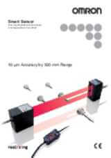
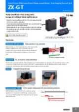
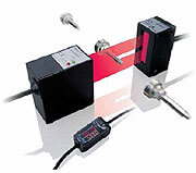
Nový inteligentní laserový mikrometr ZX-GT doplňuje řadu produktů společnosti Omron pro inteligentní laserové měření. Mikrometr ZX-GT dokáže detekovat hrany, měřit průměry předmětů a přesně vypočítávat polohy na všech druzích materiálů. Mikrometr ZX-GT je založený na technologii CCD, takže dosahuje vysoké přesnosti a rychlosti i v náročném prostředí. Průhledné předměty, odrazivé povrchy ani různé polohy nemají na výsledek vliv. Software PC Smart Monitor pomáhá se snadným nastavením a konfigurací laserového mikrometru.
- Vysoká přesnost:: 5 až 10 µm
- Vhodný pro všechny povrchy
- Velký snímací dosah: < 500 mm
- Šířka paprsku až 28 mm
- Kalkulační jednotka pro několik snímacích hlavic
Specifikace & informace pro objednání
Ordering information
Sensors
Controller
Accessories (order separately)
Set of interface unit and setup software PCs
Interface unit(RS-232C/binary output)
Setup software PCs
Calculating units
Receiver-controller extension cable
Specifications
Sensor
|
Visible semiconductor laser diode (wavelength 650 nm, CLASS 1 of EN60825-1/IEC60825-1, CLASS of FDA(21CFR 1040.10 and 1040.11) |
||||
|
0.5 mm dia.1 |
0.5 mm dia.1 |
|||
|
±0.1% F.S.2 |
||||
|
10 µm (number of process values to average: 16)3 |
||||
|
±0.01% F.S/C4 |
||||
|
ON: Short-circuited with 0 V or 1.5 V max. |
ON: Short-circuited with power supply voltage or |
|||
|
NPN open-collector output |
PNP open-collector output |
|||
|
1,000 lx (incandescent light)5 |
||||
|
Operating: 0 to 40°C, storage: -15 to 50°C (with no icing or condensation) |
||||
|
10 to 150 Hz single-amplitude: 0.75 mm for 80 min each in X, Y and Z directions |
||||
Controller
|
Measurement cycle6 |
1.5 ms (standard mode (NORM)) |
||
|
Analog output8 |
For current output: 4 to 20 mA/F.S., max. load resistance 300
Ω
|
||
|
Timing input, bank switching input, zero reset input, reset input |
ON: short-circuited with 0 V or 1.5 V max. |
ON: short-circuited with power supply voltage or |
|
|
NPN open-collector output |
PNP open-collector output |
||
|
Judgment output indicator: HIGH (orange), PASS (green), LOW (orange) |
|||
|
Interrupted beam width measurement, incident beam width measurement, outer diameter measurement, center position measurement, IC lead pitch, |
|||
|
Measured value, resolution, threshold, voltage output value, current output value (number of display digits can be changed) |
|||
|
Sample hold, peak hold, bottom hold, peak-to-peak hold, average hold, delay hold |
|||
|
Optical axis adjust mode/light intensityt writing mode, variable binary level, variable edge filter, analog output scaling |
|||
|
2 possible on up to two controllers (calculation Unit ZX-CAL2 is required for connecting controllers to each other.) A-B, A+B, width |
|||
|
Measurement cycle setting, threshold setting, hysteresis setting, initialization, key lock |
|||
|
Operating: 0 to 50°C, storage: -15 to 60°C (with no icing or condensation) |
|||
|
10 to 150 Hz single-amplitude: 0.35 mm for 80 min each in X, Y and Z directions |
|||
|
Case: PBT (polybutylene terephthalate), cover: Polycarbonate |
|||
Interface unit
1. Distance between emitter and receiver: 500 mm, measurement object at 250 mm from receiver. Glass ends of chamfer 0.1 mm or more can be detected in glass edge measurement mode. (at binary level 70%)
2. Linearity is given to be a typical error with respect to an ideal straight line when the distance between the emitter and receiver is 100 mm and light is blocked at a distance of 50 mm from the receiver. (On the ZX-GT2840_, the measurement object is measured at a distance of 20 mm from the receiver.)
3. The amount of fluctuation (±3 σ ) in the analog output when the distance between the emitter and receiver is 100 mm and a ZX-GTC_ is connected
4.
Change in the light cutoff value on one side when the distance between the emitter and receiver is 100 mm and the light is half-cutoff at a distance of 50 mm from the receiver (On the
ZX-GT2840_, the measurement object is measured at a distance of 20 mm from the receiver.)
6. The first response time is “measurement cycle x (number of samples to average setting + 1) + 1 ms” max. For the second response time onwards, the specified measurement cycle time is output.
7. The response time in the high-speed mode (FAST) for the IC lead pitch and IC lead width judgment modes is 1 ms.
11.
Normally, wire the sync output wire directly to the emitter's sync input wire and run the controller in the standard mode. On an NPN type controller, use an NPN type emitter, and on a PNP type controller, use a PNP type emitter. Wiring of the sync wires is not required when the controller is run in the high-speed mode.
(Note, however, that the controller becomes more susceptible to the influence of ambient light in this case.)
Potřebujete pomoc?
Jsme zde, abychom vám pomohli! Kontaktujte nás a naši specialisté vám pomohou najít nejlepší řešení pro vaše podnikání.
Kontaktujte nás ZX-GT
Děkujeme Vám za odeslání vašeho požádavku. Budeme Vás kontaktovat co nejdříve.
Objevili se technické potíže. Odeslání Vašeho formuláře nebylo úspěšné. Prosím přijměte naši omluvu a zkuste to znovu později. Podrobnosti: [detaily]
Nabídka pro ZX-GT
Vyplněním tohoto formuláře můžete požádat o cenovou nabídku vybraného produktu. Prosím vyplňte všechna povinná pole označená *. S vašimi osobními údaji bude nakládáno důvěrně.
Děkujeme Vám za vaši žádost o cenovou nabídku. Požadované informace Vám poskytneme co nejdříve.
Objevili se technické potíže. Odeslání Vašeho formuláře nebylo úspěšné. Prosím přijměte naši omluvu a zkuste to znovu později. Podrobnosti: [detaily]
Stahování dokumentace

_41(a)_instruction_sheet_en.jpg)